
Preface
The hot-rolled pickling coil production line of Panzhihua New Steel & Vanadium Co., Ltd. Cold Rolling Plant was completed and put into operation in 2004. According to the overall plan of Panzhihua Iron and Steel, a single-stand rolling mill unit was built in the Chengdu branch in 2006. The raw material steel coil of this mill is to be provided by the hot-rolled pickling coil production line of Panzhihua Iron and Steel Cold Rolling Plant. The product of this unit is required to use rolling oil to prevent rust, so as to be compatible with the rolling emulsion in the subsequent process. The unit has one original electrostatic oiler and one roller oiler. Because the electrostatic oiler is not effective in applying rolling oil, the original roller oiler comes from the acid-rolling combined unit of the factory. The performance of the idle equipment offline in the renovation project cannot meet the production requirements. For this reason, a 3M mill roller, a high-tech product with excellent performance, was used to transform the original roller oiling machine.
Problems Existing in the Original Roller Oiler
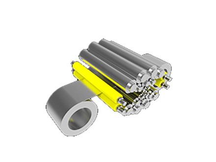
The structure principle of the roller oil spreader is shown in Figure 1.
When the oiling machine is put into use, the upper set of rollers is pressed down, and the lower set of rollers is lifted up, so that a certain wrap angle is formed between the strip steel and the oiling roller. Both the oil application roller and the oil dip roller are passive rollers, driven by strip steel. The oil spray device sprays the oil from the lubrication system onto the oil roller; by squeezing each other, the oil roller transfers the oil to the oil roller; the oil roller then evenly coats the oil on the steel strip. The excess oil is collected by the tank and flows to the recovery tank.
After the transformation of the acid-rolling combined unit, the technical performance requirements of the oil spreader have been improved. The specific parameters are shown in Table 1.
Before the transformation of the acid-rolling combined unit, in order to prevent strip-like oil-free film defects on the surface of the steel plate, the fuel injection device of the oil spreader was modified. The liquid can be sprayed more evenly on the oiled roller, thereby solving the problem of local oil-free. But the oiling machine still has the following problems:
- The width of the product is not enough: the maximum product width of the unit is 1150mm; after its transformation, the maximum width of the finished strip steel is required to be 1300mm.
- Maintenance is difficult: In this unit, there is a disc cutter in front of the oiling machine for strip steel trimming to complete the width to length. The edge of the strip after trimming has burrs, which will damage the oiling roller. The oiling roller is a felt roller, which is easy to be cut by the edge of the strip steel, resulting in lint and loosening. It needs to be replaced frequently and the maintenance period is short.
- The amount of oil applied is not easy to control: due to uneven oil application, more oil is added in order to avoid local oil-free, resulting in excessive local oil film in other parts, affecting the packaging process, and high oil consumption.
- The original lubrication system fails, its control system has low precision and it is difficult to purchase maintenance spare parts.
It can be seen that the original oiling machine cannot meet the production needs after the transformation of the hot-rolled pickling coil production line and must be transformed.
Modification
The oiling roller is the key part of the oiling machine. In order to improve the oiling quality and prolong the life of the oiling roller, a 3M millennium roller is used. In addition, due to the increase in strip width, the width of the original oil-coating cabinet, the length of the upper and lower oil-coating rollers, the length of the oil-dip roller, and the length of the oil injection device need to be increased; hydraulic lubrication and other piping need to be reconfigured, the oil-coating lubrication system and period control All systems need to be redesigned and manufactured. The details are as follows:
Upper and Lower Oiling Roller
The oiling roller is the focus of this transformation. Because the original felt roll has a short service life and the amount of oil is not easy to control, the production cost and equipment cost are both high, and it is not suitable to continue to be used. Special use of high-tech products with excellent performance-3M millennium roller.
The product performance is as follows:
- It is composed of high-strength non-woven fabric fibers. Under certain temperature, humidity and pressure, the cut part has self-healing ability. Its porous non-woven fabric structure has a certain degree of water absorption and oiliness. The oil can be indirectly coated on the coil by extrusion, and the required oil film amount can be controlled by the density of the millennium roller, the clamping pressure and the coil speed. Therefore, the effect of oiling and absorbing the surface of the coil is better than traditional rubber rollers and felt rollers.
- Porous, dirt can penetrate into the non-woven fabric structure in a small amount, so it can reduce the scratches and pollution caused to the coil.
- It has a high friction system that traditional rubber rollers, steel rollers, and felt rollers can’t match. This feature can provide enough friction to effectively prevent the roller from slipping and avoid secondary scratches on the surface of the coil.
Table 2 shows the performance comparison between 3M millennium roller and traditional rubber roller and felt roller.
The technical parameters of the 3M millennium roller used in this transformation are shown in Table 3.
Newly Made Oil-coated Lubrication System
The original lubrication system has failed due to long use time and needs to be redesigned and manufactured. The working principle of the new system is shown in Figure 2.
The system has the following characteristics:
- valve controls the loading and unloading of the pump; the excess oil flowing back from the oiling chamber flows to the recovery tank under the action of gravity; the recovered oil is filtered and sent to the main tank for reuse by the oil supply pump.
- Cleanliness control: The system is equipped with suction filter, pressure oil filter and oil recovery filter. The main fuel tank and the recovery fuel tank are also equipped with air filters to ensure the cleanliness of the oil and avoid clogging of the nozzles.
- Main fuel tank level control: real-time detection of fuel tank level, remote signal output, and interlocking control with the fuel supply pump. When the level gauge 4 reaches the upper limit, the fuel supply pump will automatically (or manually) stop fuel supply (and perform the status on the operating box). Display); when the lower limit is reached, the fuel supply pump will automatically start (or manually) to refuel: when the lower limit is reached, the fuel injection pump will stop working and give an alarm.
- Recovered fuel tank level control: real-time detection of fuel tank level, remote signal output, and interlocking control with the fuel supply pump. When the level gauge 2 reaches the upper limit, it will automatically supply fuel to the main fuel tank, and the lower limit will be alarmed; when the lower limit is reached, the fuel supply pump Automatically stop fuel supply and alarm.
- Temperature control: The main oil tank is equipped with an oil temperature detection instrument with remote signal output. The electric heater of the oil tank realizes closed-loop control. When the oil temperature is lower than 20℃, the electric heater will automatically work; when it is higher than 40℃, the heater will automatically stop. , Ensure that the oil temperature is stable within a certain range.
Modifcation of Electrical Control System
The original lubrication control system needs to be redesigned and manufactured due to low control accuracy and difficulty in purchasing maintenance spare parts. A set of PLC S7-200 control system is used alone to realize the following functions:
- Manually start the lubrication system, the fuel injection pump runs at low speed, the solenoid valve loses power, and the oil circulates in the unloaded state.
- PLC provides strip steel running analog signal (4-20mA) and solenoid valve switch signal (passive point) to form a closed loop with the DC governor. The oiling machine control cabinet is adjusted by the DC governor according to the analog signal of the strip running speed The speed of the motor controls the flow of the fuel injection pump. There is a digital display of the motor speed on the control cabinet.
- The control cabinet is equipped with manual and automatic switching functions: in manual control mode (on-site manual priority), the operator does not rely on the strip speed analog signal provided by the PLC, but the operator manually adjusts the motor speed to control the fuel injection pump . In the automatic control mode, the fuel supply of the fuel injection pump is proportional to the strip speed of the unit; when the working system fails, the standby pump is automatically started. After the lubrication system is started or when the strip speed signal provided by the PLC is not received for 10 minutes during operation, the lubrication system automatically stops running.
- System alarm, fault reset; main parameter display and parameter setting.
Other Corresponding Equipment Modification
- In order to save the time of project implementation, it was decided to use the original oiling machine to install the base. According to the original installation hole size on the base, the width was increased by 150mm, and the new oiling cabinet was designed.
- The function of the oil roller is to transfer the lubricating oil from the oil injection device to the oil roller. Only need to increase the length by 150mm according to the original structure of the oil-dipping roller. Redesign and manufacture.
- Corresponding to the transformation of the main part of the oil spreader, the original hydraulic, pneumatic, and lubricating machine body piping should also be modified and re-piped.
Post-modification Performance
The transformation of the oil spreader was completed in June 2006 and met the production requirements after it was put into production. There was no obvious damage to the 3M millennium roller, and the rest of the oiling machine was operating normally.
Due to the inherent shortcomings of the roller oiler, other units in the Panzhihua Iron and Steel Cold Rolling Plant have basically eliminated them and replaced them by electrostatic oilers. However, this transformation has achieved good results due to the use of excellent millennium rolls, making the roll oiler occupy a place in the cold rolling mill. According to the actual use of the millennium roller, it has been applied to the galvanizing line.